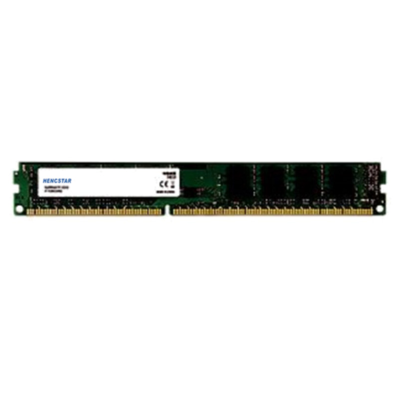
DDR3 Specifiche del modulo di memoria UDIMM
Ottieni l'ultimo prezzo| Tipo di pagamento: | L/C,T/T,D/A |
| Incoterm: | FOB,EXW,CIF |
| Trasporti: | Ocean,Air,Express,Land |

Shenzhen Hengstar Technology Co., Ltd.
| Tipo di pagamento: | L/C,T/T,D/A |
| Incoterm: | FOB,EXW,CIF |
| Trasporti: | Ocean,Air,Express,Land |
Modello: NSO4GU3AB
| Unità vendibili | : | Piece/Pieces |
4GB 1600MHz 240 pin ddr3 udimm
Cronologia delle revisioni
|
Revision No. |
History |
Draft Date |
Remark |
|
1.0 |
Initial Release |
Apr. 2022 |
|
![]()
Tabella delle informazioni di ordinazione
|
Model |
Density |
Speed |
Organization |
Component Composition |
|
NS04GU3AB |
4GB |
1600MHz |
512Mx64bit |
DDR3 256Mx8 *16 |
Descrizione
Hengstar DIMMS DDR3 SDRAM non infastiditi (moduli di memoria in linea Dram a doppia frequenza dati DRAM) sono moduli di memoria di funzionamento ad alta velocità a bassa potenza che utilizzano dispositivi DDR3 SDRAM. NS04GU3AB è un prodotto DDR3 DDR3-1600 DDR3-1600 DDR3-1600 a due ranghi X da 512 m, basato su sedici componenti FBGA da 256 m a 8 bit. L'SPD è programmato per la latenza standard JEDEC DDR3-1600 di 11-11-11 a 1,5 V. Ogni Dimm a 240 pin utilizza dita di contatto d'oro. Il DIMM non infranto SDRAM è destinato all'uso come memoria principale quando installato in sistemi come PC e workstation.
Caratteristiche
Perca potenza: VDD = 1.5V (da 1.425v a 1.575V)
VDDQ = 1.5V (da 1.425v a 1.575V)
80000MHz FCK per 1600 MB/sec/pin
8 banca interna indipendente
Latenza CAS programmabile: 11, 10, 9, 8, 7, 6
Latenza additiva programmabile: 0, Cl - 2 o Cl - 1 Clock
8-BIT Pre-FETCH
Lunghezza per scopi: 8 (interleave senza limiti, sequenziale con l'indirizzo iniziale solo "000"), 4 con TCCD = 4 che non consente una lettura o scrittura senza soluzione di continuità [al volo usando A12 o MRS]
Dati differenziali BIBI STROBE
Calibrazione interiore (auto); Auto -calibrazione interna tramite PIN ZQ (RZQ: 240 ohm ± 1%)
La risoluzione del dado utilizzando ODT PIN
Periodo di aggiornamento della media 7,8US a meno di TCASE 85 ° C, 3,9US a 85 ° C <tcase <95 ° C
Reimposta asincrona
Resotta da unità di output dati regolabile
Topologia fly-by
pcb: altezza 1,18 "(30 mm)
Rohs conforme e senza alogeno
Parametri di temporizzazione dei tasti
|
MT/s |
tRCD(ns) |
tRP(ns) |
tRC(ns) |
CL-tRCD-tRP |
|
DDR3-1600 |
13.125 |
13.125 |
48.125 |
2011/11/11 |
Tabella degli indirizzi
|
Configuration |
Refresh count |
Row address |
Device bank address |
Device configuration |
Column Address |
Module rank address |
|
4GB |
8K |
32K A[14:0] |
8 BA[2:0] |
2Gb (256 Meg x 8) |
1K A[9:0] |
2 S#[1:0] |
Descrizioni dei pin
|
Symbol |
Type |
Description |
|
Ax |
Input |
Address inputs: Provide the row address for ACTIVE commands, and the column |
|
BAx |
Input |
Bank address inputs: Define the device bank to which an ACTIVE, READ, WRITE, or |
|
CKx, |
Input |
Clock: Differential clock inputs. All control, command, and address input signals are |
|
CKEx |
Input |
Clock enable: Enables (registered HIGH) and disables (registered LOW) internal circuitry |
|
DMx |
Input |
Data mask (x8 devices only): DM is an input mask signal for write data. Input data is |
|
ODTx |
Input |
On-die termination: Enables (registered HIGH) and disables (registered LOW) |
|
Par_In |
Input |
Parity input: Parity bit for Ax, RAS#, CAS#, and WE#. |
|
RAS#, |
Input |
Command inputs: RAS#, CAS#, and WE# (along with S#) define the command being |
|
RESET# |
Input |
Reset: RESET# is an active LOW asychronous input that is connected to each DRAM and |
|
Sx# |
Input |
Chip select: Enables (registered LOW) and disables (registered HIGH) the command |
|
SAx |
Input |
Serial address inputs: Used to configure the temperature sensor/SPD EEPROM address |
|
SCL |
Input |
Serial |
|
CBx |
I/O |
Check bits: Used for system error detection and correction. |
|
DQx |
I/O |
Data input/output: Bidirectional data bus. |
|
DQSx, |
I/O |
Data strobe: Differential data strobes. Output with read data; edge-aligned with read data; |
|
SDA |
I/O |
Serial |
|
TDQSx, |
Output |
Redundant data strobe (x8 devices only): TDQS is enabled/disabled via the LOAD |
|
Err_Out# |
Output (open |
Parity error output: Parity error found on the command and address bus. |
|
EVENT# |
Output (open |
Temperature event: The EVENT# pin is asserted by the temperature sensor when critical |
|
VDD |
Supply |
Power supply: 1.35V (1.283–1.45V) backward-compatible to 1.5V (1.425–1.575V). The |
|
VDDSPD |
Supply |
Temperature sensor/SPD EEPROM power supply: 3.0–3.6V. |
|
VREFCA |
Supply |
Reference voltage: Control, command, and address VDD/2. |
|
VREFDQ |
Supply |
Reference voltage: DQ, DM VDD/2. |
|
VSS |
Supply |
Ground. |
|
VTT |
Supply |
Termination voltage: Used for control, command, and address VDD/2. |
|
NC |
– |
No connect: These pins are not connected on the module. |
|
NF |
– |
No function: These pins are connected within the module, but provide no functionality. |
Note : La tabella di descrizione del pin seguente è un elenco completo di tutti i possibili pin per tutti i moduli DDR3. Tutti i pin elencati possono non essere supportato su questo modulo. Vedere le assegnazioni dei pin per informazioni specifiche per questo modulo.
Diagramma a blocchi funzionale
4 GB, modulo 512mx64 (2Rank di X8)


Dimensioni del modulo
Vista frontale

Vista frontale

Appunti:
1. tutte le dimensioni sono in millimetri (pollici); Max/min o tipico (tipo) dove indicato.
2.Tolerance su tutte le dimensioni ± 0,15 mm se non diversamente specificato.
3. Il diagramma dimensionale è solo a riferimento.


Privacy statement: Your privacy is very important to Us. Our company promises not to disclose your personal information to any external company with out your explicit permission.
Fill in more information so that we can get in touch with you faster
Privacy statement: Your privacy is very important to Us. Our company promises not to disclose your personal information to any external company with out your explicit permission.